It’s been quite a while since the first post on this device, and a lot has happened in the meantime: Most notably, the first devices based on ipq5018 chipsets have been supported in OpenWrt by the start of this year.
Being curious about another device announced with this chipset, it was about time to dig Kevin back out and start learning about how device support works for this new subtarget in qualcommax.
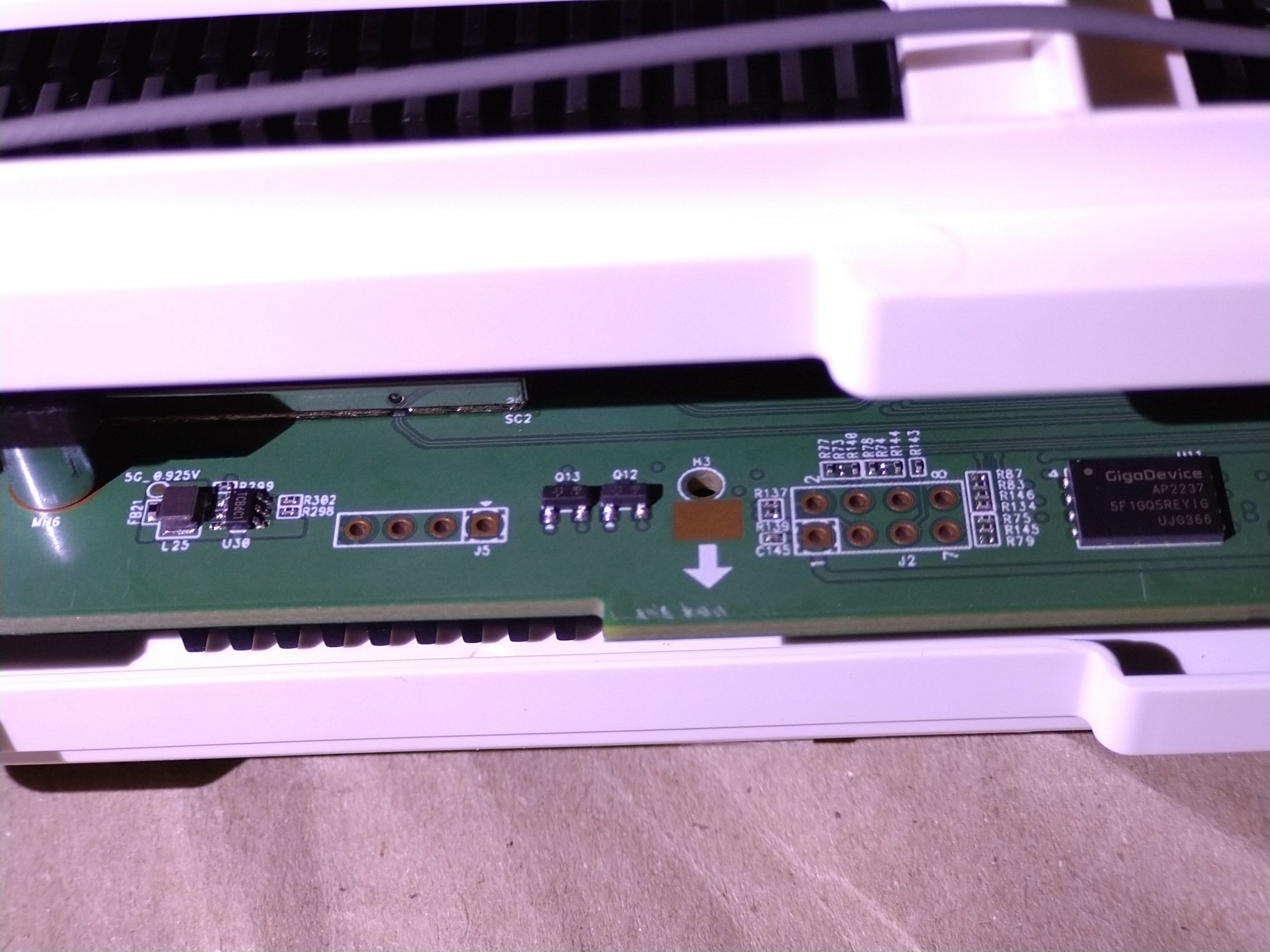
The main hassle was interfacing the SPI NAND flash, which comes in a package called WSON8, that is way more challenging to desolder (probably also glued) or even attach wires to than an SOIC-8, for example. Also no clips seem to be available, as there are no pins, but just QFN style solder pads on the sides.
The pinout is the same as with the “25” style SPI NOR flashes though, so a CH341A-based programmer can be used with the tool SNANDer from https://github.com/Droid-MAX/SNANDer.
With all 8 lines (including 3.3V) connected, the AMS1117 in the programmer turned quite hot, trying to supply the whole board, but weirdly the flash chip was still detected at some point (after attaching and then removing the router’s power supply). I had no luck with the flash chip’s ECC though, so I went for disabling ECC: SNANDer -I -r dump.bin.
This took a while, but even with several attempts there were always flipped bits at varying locations in the output, maybe the wires were too long, or the (apparently hardcoded) SPI frequency should be decreased in the tool?
This would not have been a reliable way of flashing a full OpenWrt image after all, and even from the flash dump it was hard to find a definitive mtd partition layout (both binwalk and tools for reading UBI seemed to give up on the damaged flash dump, even after stitching a combined “best of three” image which had at least most of the bitflips from single transmission errors fixed).
Another attempt was trying to figure out what those lines on the 8-pin connector J2 next to the SPI flash are for. There is a device called “JTAGulator” which is quite expensive though, but it turned out people have ported the basic idea of brute-forcing JTAG pins to more readily available hardware platforms, i.e. RP 2040 based boards: https://github.com/Aodrulez/blueTag
But still no luck with this, maybe JTAG is just being disabled during the very early stages of uboot execution, or it needs more time to try all possible permutations, but there seemed to be no way to halt the CPU at that point, i.e. before pins would be muxed as GPIOs or for use with other peripherals.
So what else could we try for breaking into this thing, e.g. obtaining a uboot shell or something?
With wires attached to the NAND flash already, the idea of glitching seemed like a feasible thing to try next: When shorting flash chip data pins very early during boot, nothing is printed to the serial console, as the hardware boot ROM cannot even successfully load the `SBL1` partition from NAND.
When glitching later, we would see the serial output of SBL1, but get a bootloop when SBL1 could not successfully load uboot from the APPSBL partition.
Quickly after uboot was loaded, messing with flash data lines causes uboot to fail reading its environment from APPSBLENV (checksum fail), and this will result in interesting behaviour:
qpic_nand_read_page_scope_multi_page: ecc failure while reading from 480000
NAND read from offset 480000 failed -74
*** Warning - readenv() failed, using default environment
uboot would still boot the kernel, but fall back to its hardcoded default environment, which also affects the bootargs variable that contains the kernel command line. As a result, we finally get a “real” bootlog with kernel messages, including the mtd layout =)
[ 3.824696] nand: device found, Manufacturer ID: 0xc8, Chip ID: 0x41
[ 3.824723] nand: ESMT GD5F1GQ5REYIG SPI NAND 1G
[ 3.830848] nand: 128 MiB, SLC, erase size: 128 KiB, page size: 2048, OOB size: 128
[ 3.835718] qcom-nandc 79b0000.qpic-nand: x4 mode enabled already remotely
[ 3.845963] qcom-nandc 79b0000.qpic-nand: Error in reading max io macro clock from dts
[ 3.849886] 22 fixed-partitions partitions found on MTD device qcom_nand.0
[ 3.857733] Creating 22 MTD partitions on "qcom_nand.0":
[ 3.864536] 0x000000000000-0x000000080000 : "0:SBL1"
[ 3.871459] 0x000000080000-0x000000100000 : "0:MIBIB"
[ 3.876462] 0x000000100000-0x000000140000 : "0:BOOTCONFIG"
[ 3.881102] 0x000000140000-0x000000180000 : "0:BOOTCONFIG1"
[ 3.886559] 0x000000180000-0x000000280000 : "0:QSEE"
[ 3.892697] 0x000000280000-0x000000380000 : "0:QSEE_1"
[ 3.897932] 0x000000380000-0x0000003c0000 : "0:DEVCFG"
[ 3.902120] 0x0000003c0000-0x000000400000 : "0:DEVCFG_1"
[ 3.907269] 0x000000400000-0x000000440000 : "0:CDT"
[ 3.912677] 0x000000440000-0x000000480000 : "0:CDT_1"
[ 3.917385] 0x000000480000-0x000000500000 : "0:APPSBLENV"
[ 3.922863] 0x000000500000-0x000000640000 : "0:APPSBL"
[ 3.928908] 0x000000640000-0x000000780000 : "0:APPSBL_1"
[ 3.933866] 0x000000780000-0x000000880000 : "0:ART"
[ 3.939155] 0x000000880000-0x000000900000 : "0:TRAINING"
[ 3.943253] 0x000000900000-0x000003300000 : "rootfs"
[ 3.985568] mtd: device 15 (rootfs) set to be root filesystem
[ 3.985883] mtdsplit: no squashfs found in "rootfs"
[ 3.990325] 0x000003300000-0x000005d00000 : "rootfs_1"
[ 4.033480] 0x000005d00000-0x000006600000 : "0:DVCFG"
[ 4.042461] 0x000006600000-0x000006f00000 : "0:DVCFG_1"
[ 4.051558] 0x000006f00000-0x000007f00000 : "0:LOG"
[ 4.066738] 0x000007f00000-0x000007f80000 : "0:DVFLAG"
[ 4.068329] 0x000007f80000-0x000007fc0000 : "0:DVMON"
[ 4.072864] spi_qup 78b5000.spi: IN:block:16, fifo:64, OUT:block:16, fifo:64
[ 4.077044] spi-nor spi0.0: unrecognized JEDEC id bytes: 00 00 00 00 00 00
of course they did not even care about disabling the SPI NOR flash here…
Looking at the uboot environment at 0x480000, the bootcmd variable initially contains
bootargs=console=ttyMSM0,115200n8
bootcmd=bootipq; bootswap
bootdelay=1
bootdelay_=0
so technically we can just try to prepend tftpboot and bootm here, fix the crc32 header (checksum over the environment variables starting at 0x4, zero-terminated strings, file terminated by two 0x00 bytes which are included in the crc32, rest padded with 0xFF).
Writing stuff back to the flash was a bit more challenging though (with the flash chip spuriously supplied via the spi programmer; reading was easier as it requires much less power).SNANDer -a 0x480000 -l 0x20000 -w appsblenv_patched.bin
Eventually it somehow worked, though I couldn’t say specifically how to reproduce it – it must have been a combination of padding the rest of the environment with 0xFF, erasing the flash area first in a separate command (using -e with SNANDer) and just a bit of trial and error. I definitely recommend desoldering the flash chip if anyone would like to attempt this!
Eventually, the contents read back identical, but still it would not boot: There was an error about an ECC failure when reading the uboot environment printed to the serial console, and it still booted OEM firmware using the default environment, even though a repeated readout with the SPI programmer revealed the environment was exactly the one I had flashed. So this must have been some internal error in the flash memory controller (which has been writing stuff under conditions way out of spec), but after a full boot and restart, this was fixed…
And then suddenly this happened:
PCI Link Intialized
PCI Link Intialized
No ethernet found.
Wrong Image Format for bootm command
ERROR: can't get kernel image!

Net:   cmbblk is stable 5
MAC0 addr:0:11:22:33:44:55
PHY ID1: 0x4d
PHY ID2: 0xd0c0
MAC1 addr:0:11:22:33:44:56
PHY ID1: 0x4d
PHY ID2: 0xd101
board_update_caldata: Unable to find slot-Id, Default CapIn/CapOut values used
, eth0, eth1
IPQ5018#
“No ethernet found” means that my tftpboot command injected to the environment was actually being called, and there was no link on any of the two network ports at that time, so it aborted, resulting in bootm trying to boot from unitialized RAM (“Wrong Image Format for bootm command”), and eventually we get what the initial glitching attemps failed to provide: a uboot shell!
IPQ5018# help
?       - alias for 'help'
ar8xxx_dump- Dump ar8xxx registers
base    - print or set address offset
bdinfo  - print Board Info structure
bootelf - Boot from an ELF image in memory
bootipq - bootipq from flash device
bootm   - boot application image from memory
bootp   - boot image via network using BOOTP/TFTP protocol
bootswap- bootswap from flash device
bootvx  - Boot vxWorks from an ELF image
bootz   - boot Linux zImage image from memory
canary  - test stack canary
chpart  - change active partition
cmp     - memory compare
coninfo - print console devices and information
cp      - memory copy
crc32   - checksum calculation
dhcp    - boot image via network using DHCP/TFTP protocol
dm      - Driver model low level access
echo    - echo args to console
editenv - edit environment variable
env     - environment handling commands
erase   - erase FLASH memory
exectzt - execute TZT

exit    - exit script
false   - do nothing, unsuccessfully
fatinfo - print information about filesystem
fatload - load binary file from a dos filesystem
fatls   - list files in a directory (default /)
fatsize - determine a file's size
fatwrite- write file into a dos filesystem
fdt     - flattened device tree utility commands
flash   - flash part_name
        flash part_name load_addr file_size

flasherase- flerase part_name

flinfo  - print FLASH memory information
fuseipq - fuse QFPROM registers from memory

go      - start application at address 'addr'
gpio    - query and control gpio pins
help    - print command description/usage
i2c     - I2C sub-system
imxtract- extract a part of a multi-image
ipq5018_mdio- IPQ5018 mdio utility commands
ipq_mdio- IPQ mdio utility commands
is_sec_boot_enabled- check secure boot fuse is enabled or not

itest   - return true/false on integer compare
loop    - infinite loop on address range
md      - memory display
mii     - MII utility commands
mm      - memory modify (auto-incrementing address)
mmc     - MMC sub system
mmcinfo - display MMC info
mtdparts- define flash/nand partitions
mtest   - simple RAM read/write test
mw      - memory write (fill)
nand    - NAND sub-system
nboot   - boot from NAND device
nfs     - boot image via network using NFS protocol
nm      - memory modify (constant address)
part    - disk partition related commands
pci     - list and access PCI Configuration Space
ping    - send ICMP ECHO_REQUEST to network host
printenv- print environment variables
protect - enable or disable FLASH write protection
qpic_nand- Switch between SBL and Linux kernel page on 4K NAND Flash.
reset   - Perform RESET of the CPU
run     - run commands in an environment variable
runmulticore- Enable and schedule secondary cores
saveenv - save environment variables to persistent storage
secure_authenticate- authenticate the signed image

setenv  - set environment variables
setexpr - set environment variable as the result of eval expression
sf      - SPI flash sub-system
showvar - print local hushshell variables
sleep   - delay execution for some time
smeminfo- print SMEM FLASH information
source  - run script from memory
test    - minimal test like /bin/sh
tftpboot- boot image via network using TFTP protocol
tftpput - TFTP put command, for uploading files to a server
true    - do nothing, successfully
tzt     - load and run tzt

uart    - UART sub-system
ubi     - ubi commands
usb     - USB sub-system
usbboot - boot from USB device
version - print monitor, compiler and linker version
zip     - zip a memory region
IPQ5018# printenv
baudrate=115200
bootargs=root=/dev/nfs nfsroot=: ip=::::::off
bootcmd=bootp; setenv bootargs root=/dev/nfs nfsroot=${serverip}:${rootpath} ip=${ipaddr}:${serverip}:${gatewayip}:${netmask}:${hostname}::off; bootm
bootdelay=5
eth2addr=00:11:22:33:44:55
eth3addr=00:11:22:33:44:56
ethact=eth0
fdt_high=0x4A400000
fdtcontroladdr=4a9d4004
flash_type=11
machid=8040004
serial_num=DVW632IX0000012345
soc_hw_version=20180101
soc_version_major=1
soc_version_minor=1
stderr=serial@78AF000
stdin=serial@78AF000
stdout=serial@78AF000

Environment size: 559/262140 bytes
IPQ5018#
Great, so it’s finally time to build an initramfs and feed it to uboot via ttpboot and see if it boots…
Since expectations were high at this point, the eventual frustration was even bigger: I currently can no longer get this thing to boot past the SBL1 output at all, it seemes quite bricked, maybe actual hardware damage this time. I might try reflashing SBL1 or APPSBL again the same way, but it was cumbersome already the last time, and how could I be safe my backup is actually a perfect image without bitflips during transmission (ubootenv has a crc32 which I had to reconstruct anyways)?
One thing I noticed – way too late, obviously: The flash chip runs at 1.8V, not 3.3V.
Guess I have used up most of the magic smoke by now. But it might be hardware damage in some other part of the router.
So I guess this project is no longer about OpenWrt now, but generic hardware debugging and repair, probably starting with a thermal camera… so stay tuned, at least the intention of learning something about the ipq50xx target was partly fulfilled =)