Davolink DVW-632 aka “Kevin”: Teardown of the Minions router (part 1)

Every once in a while, a piece of hardware goes viral for standing out from the competition in a certain aspect. For consumer-grade wireless routers, it seems case designers have mostly been looking at Sci-Fi movies for inspiration over the past decades, until a company named Davicom chose to license a pair of well-known characters from a much different genre of movies:

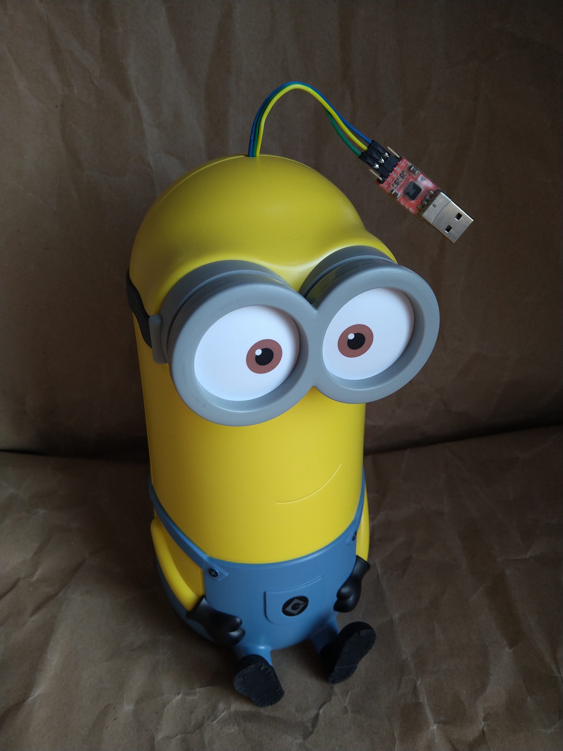
Two models are available: The smaller model DVW-642 (“Bob”) is an AX1800 dual-band wireless router, while the much larger DVW-632 (“Kevin”) is an AX5400 tri-band device, which even supports the quite new 6 Ghz band known as Wi-Fi 6E.

There is little information available on the hardware internals on these yet, the FCC filings available for Kevin do not even contain internal photos (yet?), there is only the label sample and a test setup showing a view on the PCB from the distance:
https://fccid.io/RZEDVW-632/

However, a Reddit user simply asked Davolink support for information on the chipsets:

https://www.reddit.com/r/HomeNetworking/comments/19bku93/comment/kitdu0x/

And it turns out Bob is based on a Realtek chipset, which currently does not have a high chance of getting OpenWrt support anytime soon.

However, Kevin is supposed to be based on the quite new Qualcomm Max OpenWrt target, specifically using the IPQ5018 chipset – which is not exactly supported yet, however that one looks way more like a work-in-progress at the moment, considering there are similar chipsets in the target, which is already part of OpenWrt, and there is also ongoing discussion on devices using IPQ5018, e.g. from Linksys:
https://forum.openwrt.org/t/ipq5018-potential-future-support-for-linksys-mx2000-atlas-6-mx5500-atlas-6-pro/164055/

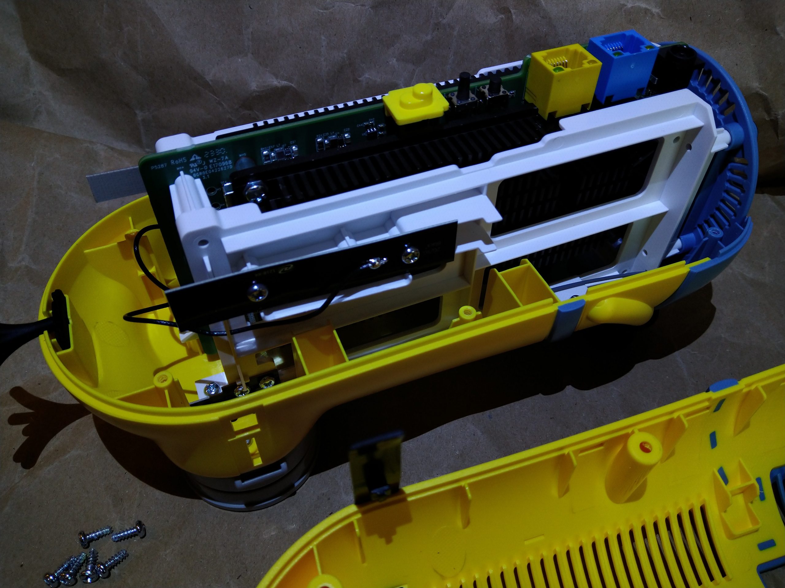
The case for Kevin opens very easily, only a few screws need to be removed to access the inner assembly, consisting of the PCB, massive heatsinks and a white plastic frame. After all, this design seems quite modular, suggesting the same hardware could be re-used for various other styles of profitable contemporary merchandise.

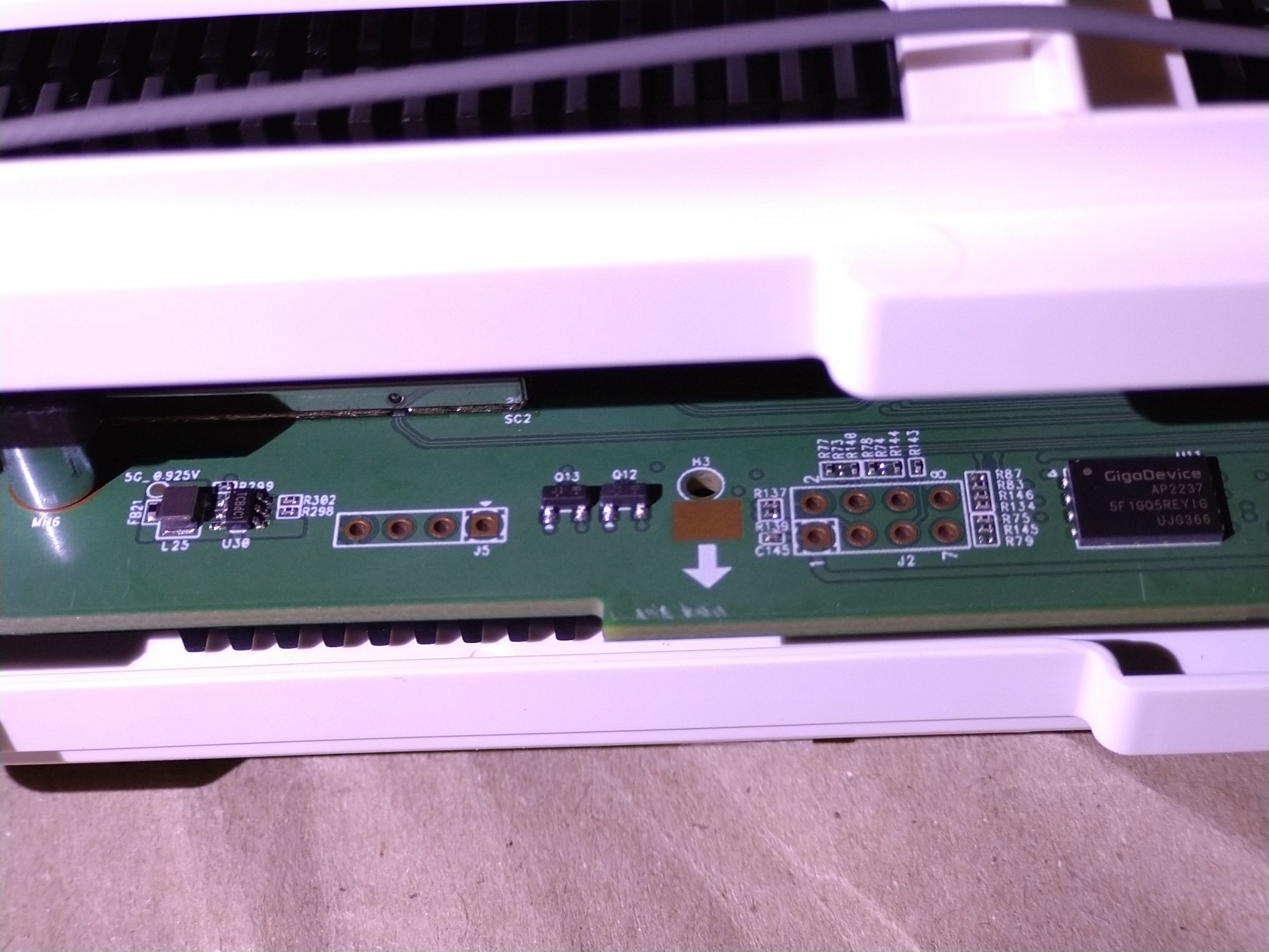
There is a TTL UART header to the left, with Pin 4 being GND and both data lines in the center:

Unfortunately, there’s not really much to see during boot, and I found no way to interrupt the bootloader yet:


Format: Log Type - Time(microsec) - Message - Optional Info
Log Type: B - Since Boot(Power On Reset),  D - Delta,  S - Statistic
S - QC_IMAGE_VERSION_STRING=BOOT.BF.3.3.1.1-00075
S - IMAGE_VARIANT_STRING=MAACANAZA
S - OEM_IMAGE_VERSION_STRING=CRM
S - Boot Config, 0x000002c5
B -       127 - PBL, Start
B -      1560 - bootable_media_detect_entry, Start
B -      3647 - bootable_media_detect_success, Start
B -      3651 - elf_loader_entry, Start
B -      8822 - auth_hash_seg_entry, Start
B -      9183 - auth_hash_seg_exit, Start
B -    103041 - elf_segs_hash_verify_entry, Start
B -    172705 - PBL, End
B -    142069 - SBL1, Start
B -    203435 - GCC [RstStat:0x0, RstDbg:0x600000] WDog Stat : 0x4
B -    211548 - clock_init, Start
D -      7564 - clock_init, Delta
B -    219295 - boot_flash_init, Start
D -     15006 - boot_flash_init, Delta
B -    234362 - boot_config_data_table_init, Start
D -      4697 - boot_config_data_table_init, Delta - (575 Bytes)
B -    242139 - Boot Setting :  0x00030618
B -    248483 - CDT version:2,Platform ID:8,Major ID:4,Minor ID:0,Subtype:4
B -    255224 - sbl1_ddr_set_params, Start
B -    256657 - Pre_DDR_clock_init, Start
B -    262513 - Pre_DDR_clock_init, End
B -    904721 - do ddr sanity test, Start
D -        61 - do ddr sanity test, Delta
B -    909388 - Image Load, Start
D -    244854 - QSEE Image Loaded, Delta - (580996 Bytes)
B -   1155096 - Image Load, Start
D -     13908 - DEVCFG Image Loaded, Delta - (13592 Bytes)
B -   1169065 - Image Load, Start
D -    182085 - APPSBL Image Loaded, Delta - (433660 Bytes)
B -   1351241 - QSEE Execution, Start
D -        30 - QSEE Execution, Delta
B -   1357707 - SBL1, End
D -   1218292 - SBL1, Delta
S - Flash Throughput, 2441 KB/s  (1029495 Bytes,  421684 us)
S - DDR Frequency, 800 MHz
S - Core 0 Frequency, 800 MHz


U-Boot 2016.01-svn6050 (Nov 28 2022 - 10:45:07 +0000)

cmbblk is stable 5
ART partition read failed..
MAC0 addr:0:11:22:33:44:55
PHY ID1: 0x4d
PHY ID2: 0xd0c0
MAC1 addr:0:11:22:33:44:56
PHY ID1: 0x4d
PHY ID2: 0xd101
board_update_caldata: Unable to find slot-Id, Default CapIn/CapOut values used
QPIC controller support serial NAND
Serial Nand Device Found With ID : 0xc8 0x41
Serial NAND device Manufacturer:GD5F1GQ5REYIG
Device Size:256 MiB, Page size:2048, Spare Size:128, ECC:8-bit
DAVO_TODO : [qpic_spi_nand_config:1462] dev->id=41c841c8 dev->vendor=c8
sdhci: Node Not found, skipping initialization
PCI Link Intialized
PCI Link Intialized

Starting kernel ...

131072+0 records in
131072+0 records out
131072 bytes (128.0KB) copied, 0.822810 seconds, 155.6KB/s
131072+0 records in
131072+0 records out
131072 bytes (128.0KB) copied, 0.824732 seconds, 155.2KB/s
131072+0 records in
131072+0 records out
131072 bytes (128.0KB) copied, 0.775230 seconds, 165.1KB/s
Loading cnss2:  bdf_integrated=0x24 bdf_pci0=0x60 bdf_pci1=0xb0
mount: can't find /lib/firmware/IPQ5018/BT_FW in /etc/fstab
BT FW mount is failed
 WIFI FW mount is successful
acfg_tool: Issuing blocking call to wait for events

========= FW INFO =========
2x2
jenkins
2023-09-15 12:39:25
DVW-632X
r7331
83e9805dded1d4e3e22fc60c1f146281
1.00.04
Primary Boot 0
===========================
----------------------------------- start_event_vap() - start(wifi0)
/tmp/config/fastwifi_cfg.tgz: OK
tmp/fastwifi_wifi0
tmp/fastwifi_wifi1
tmp/fastwifi_wifi2
var/run/hostapd-ath0.conf
var/run/hostapd-ath01.conf
var/run/hostapd-ath1.conf
var/run/hostapd-ath11.conf
var/run/hostapd-ath2.conf
var/run/hostapd-ath21.conf
Start wi-fi configuration wifi0
----------------------------------- start_event_vap() - start(wifi1)
Start wi-fi configuration wifi1
----------------------------------- start_event_vap() - start(wifi2)
Start wi-fi configuration wifi2
start config vap vap_bh0
error_handler received : -22
Failed to send message to driver Error:-22
start config vap vap_bh1
Following channels are blocked from Channel selection algorithm
 -band 2[52] [56] [60] [64] [100] [104] [108] [112] [116] [120] [124] [128] [132] [136] [140] [144] [149] [153] [157] [161] [165]
skip wifi reload. fast boot in progress
error_handler received : -22
Failed to send message to driver Error:-22
start config vap vap_bh2
Following channels are blocked from Channel selection algorithm
 -band 3[1] [5] [9] [13] [17] [21] [25] [29] [33] [41] [45] [49] [57] [61] [65] [73] [77] [81] [89] [93] [97] [105] [109] [113] [121] [125] [129] [137] [141] [145] [153] [157] [161] [169] [173] [177] [185] [189] [193] [201] [205] [209] [213] [217] [221] [225] [229] [233]
error_handler received : -22
Failed to send message to driver Error:-22
OK
start config vap vap00
OK
start config vap vap10
OK
start config vap vap20
OK
----------------------------------- start_event_vap() - end(wifi0) -  18 seconds
OK
----------------------------------- start_event_vap() - end(wifi1) -  18 seconds
OK
 WIFI FW mount is successful
OK
**** Platform Name: ap-mp03.5-c1 *****
Run REPACD
Copy ART caldata from /dev/mtdblock13 to /tmp/virtual_art.bin
----------------------------------- start_event_vap() - end(wifi2) -  21 seconds
#### easy mesh setup : controller ####
----------------------------------- ezmesh stop_service() - start
----------------------------------- ezmesh stop_service() - end - 0 seconds
----------------------------------- ezmesh start_service() - start
ezmesh: starting daemon
----------------------------------- ezmesh start_service() - end - 1 seconds
----------------------------------- wsplcd stop_service() - start
----------------------------------- wsplcd stop_service() - end - 0 seconds
----------------------------------- wsplcd start_service() - start
wsplcd: starting daemon
----------------------------------- wsplcd start_service() - end - 8 seconds
### Integrity check is passed for SHA-256 ###

We also see a GigaDevice GD5F1GQ5REY1G SPI NAND flash, with pins easily accessible without further disassembly. Here’s the datasheet:

https://www.gigadevice.com.cn/Public/Uploads/uploadfile/files/20230322/DS-00888-GD5F1GQ5UExxG-Rev1.5.pdf

So the next step from here would most probably be dumping the contents, although there is a good chance everything might be encrypted in there…

Yealink IP phones and Sennheiser DW Pro wireless headsets – what’s the magic within the EHS36 box?

If you’ve ever come across wireless headsets for office phones, you might have noticed that “wireless” in this case actually results in a lot more wires on your desk than using a regular wired headset: At least the charging / base station will need an additional power supply, and maybe also an adapter cable to fit the particular phone’s headset jack, since those base stations are rarely sold in multiple variants, tailored to a specific phone model, unlike the most simple wired headsets.

Now there’s one more advantage to wireless than just reducing the chance of accidentally pulling on the cable with an arm (or office chair): You can even leave the desk during calls. Thus it would be great to pickup and hangup calls remotely with a button on the headset – but how should the base station then signal this to the phone?

In mobile phones, this kind of button was considered for wired headsets right from the beginning: The de-facto standard means simply shorting the MIC+ line to GND (directly or with a certain resistor value to distinguish between additional functions like track skipping or volume control).

However, this was never a requirement for desk phones, so the information about ringing, accepting a call or hanging up usually needs to be transmitted out-of-band: Back in the days of analog phones, the most common approach involved mechanical handset lifters that would actually physically move the handset upwards from the phone, so the hook switch would be released or closed when the user presses the button on the headset, thus accepting the call or hanging up.

While this “standard” used to be widely compatible (it just needed to fit the gap underneath the handset), it seemed reasonable for manufacturers of modern ISDN and IP phones to come up with some less hardware-intensive solution – the “Electronic Hook Switch” (EHS).

Obviously, there could not be a common global standard for EHS functionality, but you will probably deal with one of the following (mostly country- or vendor-specific) flavours:

  • DHSG (“Drahtlose Hör-/Sprech-Garnitur”, formal German term for “wireless headset”) – probably the most widely deployed standard worldwide by now
  • AEI (“Additional Equipment Interface”) – by Avaya
  • HHC (“Headset Hookswitch Control”) – for Cisco IP phones
  • MSH (“Microphone Short Hook”, as mentioned above for mobile phones, will short the MIC line to GND to signal pickup / hangup) – available in some Alcatel phones
  • RHL (“Remote Handset Lifter”, apparently standardized interface for mechanical lifters as mentioned above)

I recently had the chance to play with some Sennheiser DW Pro DECT Headsets at the office – they offer DHSG, MSH and a (proprietary?) Handset Lifter. Our phones are Yealink T46G that do not come with EHS functionality out of the box, but you are supposed to purchase the $40 “EHS36” adapter box by Yealink, which is meant to be compatible with several wireless headset manufacturers (it even comes with a bunch of cables), including Sennheiser (in DHSG mode).

While there seems to be nothing wrong with purchasing one of those adapters for each desk, users report they would crash every once in a while and need to be re-plugged. Also it just made me curious that there is absolutely no information about pinouts or even protocols out there yet, not even a picture of the PCB… So here it is:

Yealink EHS36 PCB
Yealink EHS36 PCB

The 6P6C (RJ-12) connector on the right goes into the EXT port of the phone through a 1:1 modular cable.
For Sennheiser, a Y-Cable is included that connects the 8P8C port on the base with the 8P8C (RJ-45) port on the EHS36 (left) and the 4P4C (RJ-9) analog headset connector on the phone. Basically, Pins 3-6 for analog audio go into the Yealink phone in reverse order, while Pins 1, 2, 7 and 8 (DHSG Control Pins) go into Pins 3-6 (in this order) of the EHS36 8P8C connector.

For the detailed DHSG pinout, please see the innovaphone wiki:
http://wiki.innovaphone.com/index.php?title=Howto:DHSG_pin_assignment
The specifications are also available for download from there:
http://wiki.innovaphone.com/index.php?title=Howto:DHSG_headset_specification

There’s also some info (in German) about DHSG Y-Cables here, the one for Sennheiser should be similar to this one: http://fschreiner.de/?p=168

I soldered some 0.1″ pin headers to the modular jack pins on the back of the PCB to capture the signalling between phone and headset base while making some test calls.

The DHSG part looks quite straightforward and can also be found in the specifications above:

DHSG / EHS wireless headset serial bus protocol signalling / commands specification

8P8C pinout at EHS36 (only 3-6 seem to be connected):

Pin 3: GND
Pin 4: DHSG RX (“Bus Send”: headset -> EHS36)
Pin 5: +3.3V
Pin 6: DHSG TX (“Bus Receive”: EHS36 -> headset)

Due to the pause after each bit, it will not work with standard 8 bit hardware UART though.

However I will focus on the interface between phone and EHS36 here:

Here we have SPI with CPOL = 1, CPHA = 0 (“Mode 2”) and a variable bit count, so you probably cannot use most of the hardware implementations available in microcontrollers for this part either, since most of them can only handle fixed 8 bit data chunks.
There’s also an LDO voltage regulator on board that generates 3.3V for the logic levels from the phone’s 5V supply.

6P6C Pinout at EHS36 (conntected to phone’s EXT port):

Pin 1: MISO
Pin 2: MOSI
Pin 3: SS
Pin 4: GND
Pin 5: Vin (+5V)
Pin 6: SCLK

Let’s start with the most frequent signal:
Exactly once per second, the phone will send a 15bit poll message to the EHS box:

15 bit poll:
MOSI: 101100001100000
MISO: 000000000000101

(it seems that somewhere between bit 9 and 11 the EHS36 eventually decides to reply with …101)

Periodic
Periodic “poll” signal (1 Hz) between Yealink T46G phone and EHS36

The same “poll” also occurs in between the 1Hz interval, directly before any other command will be sent.

So let’s ask the EHS36 to signal an incoming call to the headset: On SPI we will have the above “poll” followed by another message (/SS released shortly in between!) that is 21bits in length:

21 bits ring:
MOSI: 101000001000000000010
MISO: 000000000000000000000

The EHS36 then signals DHSG Code 1 to the headset base, and you can hear the ringing indicator in the earpiece.

Now what if you press pickup on the headset?
Upon receiving DHSG Code 2, EHS36 will set MISO high, which makes the phone immediately pull /SS low and start generating the clock for a transfer:

At first we see the same “poll” command as above, however MISO is still high during the first 12 bits:

MOSI: 101100001100000
MISO: 111111111111101 (apparently, only the last 3 bits are considered as acknowledge from EHS36 to the polling?)

After that, /SS will be released shortly and a new 19bits transfer is started – the phone will read the command from EHS:

19 bits pickup:
MOSI: 0111111111111111111
MISO: 1110100000100011001

EHS36 now confirms with DHSG Code 2 and the call is being accepted by the phone; curiously this is followed by two more “poll” commands with sometimes very delayed SPI clock (phone seems to be busy handling the call). After several hundred milliseconds to establish the call, the phone notifies the headset about the successfull connection again with DHSG Code 2 (this will also happen when you press accept on the phone rather than headset, or after you have dialled a number and the remote party accepts):

Again, we see a “poll” command followed by a signal that is 21 bits in length:

21 bits call established:
MOSI: 101000001000000000000
MISO: 000000000000000000000

EHS36 logic signals when picking up a call by pressing the headset button

What’s missing? Hanging up by pressing the headset button!

If the headset base sends DHSG Code 1 during a call, exactly the same will happen on SPI side as for pickup:
A “poll” with first 12 bits MISO high, followed by 19 bits pickup command. This is followed by two “regular poll” commands.
The base then receives DHSG Code 3 as an indicator that the call has been terminated.

Where to go from here?

Using the information above, it should be theoretically possible to build your own EHS-adapter for Yealink <-> DHSG, though this would most probably not be cheaper than buying the original one in the small scale.

However, you could add some nice features like Busy Light Indication – think of a little LED sign on your desk that shows clearly whether you are available or not?

There seems to be no busy light on the market yet that natively uses the EXT port on Yealink phones – all that money can buy at the moment will use workarounds like monitoring the state of the microphone audio line between phone and headset – through another little black plastic box on your desk… *sigh*

For the kuando Busylight Combi, for example, there’s even a dual version that allows you to use *either* handset or external headset, by looping both microphone lines through the box…
http://www.plenom.com/support/kuando-busylight-combi/installation/

So stay tuned for my future attempts of putting EHS, Sennheiser Y-Cable and Busy Light Ddetection all into one little box 🙂